|
|
|
Categories
|
|
Information
|
|
Featured Product
|
|
|
 |
|
|
There are currently no product reviews.
 ;
Awesome quality manual. You really saved my bacon with this one. Was looking for some specific information with regards to my "new" vintage VCR that didn't come with the owners manual. This site is truely a goldmine of available manuals. The quality of the scans are top notch.
Thank-you so much for this awesome manual. If you're looking for this Sony SL-HF400 owners manual, this is the one you NEED to buy. Definitely worth the money.
;
The manual was made available promptly. I is a clean scan of the original. I had no problem downloading it. The scan was well centered and cleanly formatted. It is as good a product as can be had without being the original document.
 ;
Received downlink in less then 8 hours, Item was in good copy condition, and told me how to program the clock timer. The price was very resonable, and the process was very automated and was GREAT to work with.
;
Fast service, document is OK. Thanks! Searched for it long time.
;
I was very pleased with the manual I got for my amateur (ham) radio. Without it I could not figure out how to input and/or change the P/L setting on my radio. It drove me nuts as the radio was essentially useless. That all changed when my manual came. Then it took only minutes and I was done. Now my radio works fine. This is an exceptionally good resource as it's a very easy and user friendly download. Thank you very much! Dziękujemy za!
Thank you
for purchasing a JBL Loud + Clear amplifier. In order that we may better serve you should you require warranty service on your new amplifier, please retain your original purchase receipt and return the enclosed warranty registration card. Important: Installation of automotive stereo components can require extensive experience in performing a variety of mechanical and electrical procedures. Although these instructions explain, in a general sense, how to install Loud + Clear amplifiers, they may not show the exact installation methods for your particular vehicle. If you feel you lack the tools or necessary experience, ask your authorized JBL car-audio dealer about professional installation options.
Installation Warnings and Tips � Always wear protective eyewear when using tools. � Turn off all audio systems and other electrical devices before you start. � Disconnect the negative (�) lead from your vehicle�s battery. � Check clearances on both sides of a planned mounting surface before drilling any holes or installing any screws. Remember that the screws can extend behind the surface. � At the installation sites, locate and make a note of all fuel lines, hydraulic brake lines, vacuum lines and electrical wiring. Use extreme caution when cutting or drilling in and around these areas. � Before drilling or cutting holes, use a utility knife to remove unwanted fabric or vinyl to keep material from snagging in a drill bit.
� When routing cables, keep inputsignal cables away from power cables and speaker wires. � When making connections, ensure that they are secure and properly insulated. � If the amplifier�s fuse must be replaced, use only the same type and rating as that of the original. Do not substitute another kind.
Warning: Playing loud music in an automobile can permanently damage your hearing as well as hinder your ability to hear traffic. We recommend listening at low levels while in your car. JBL accepts no liability for hearing loss, bodily injury or property damage resulting from use or misuse of this product.
Choosing a Location and Mounting the Amplifier
Amplifiers need air to stay cool. Suitable locations are under seats (provided the amplifier doesn�t interfere with the seat-adjustment mechanism), in the trunk or in any location that provides enough air for the amp to cool itself. Do not mount the amplifier with the heat-sink fins facing downward; this makes convection cooling of the amplifier impossible. Mount the amplifier so that it is not damaged by the feet of back-seat passengers or shifting cargo in the trunk. Mount the amplifier so that it remains dry � never mount an amplifier outside the car or in the engine compartment. Using the amplifier as a template, mark the location of the mounting holes on the mounting surface, drill pilot holes and attach the amplifier to the mounting surface with screws. Make sure the amplifier is mounted securely.
If you are bridging the amplifier, connect the speaker wires to the terminals marked �bridged,� observing proper polarity. The total impedance of the speaker system connected to the amplifier must be at least four ohms in bridged mode. If you are running the amp in Tri-Mode (stereo and mono simultaneously), connect the satellite speakers to the speaker connector as you would a pair of stereo speakers. Connect the subwoofer to the terminals marked �bridged.� Refer to the chart below to determine the capacitor and inductor values you�ll need to route bass signals to the woofer, and the midrange and high frequencies to the satellite speakers. These passive crossover components will also ensure that the impedance of the speaker system doesn�t drop below two ohms.
FREQUENCY
Crossover
INDUCTOR
6dB/oct. LP (4 ohm) 8.0mH 6.4mH 5.0mH 4.2mH 3.6mH 3.2mH
CAPACITOR
6dB/oct. HP (4 ohm) 530µF 400µF 318µF 265µF 227µF 198µF
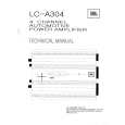
Wiring the Power Connections
Refer to Figures 1�4 for connector locations. Use at least 10-gauge wire for power and ground connections. For power, remote and ground connections strip off one end of each jacket to reveal bare wire for insertion into the barrier-strip connectors. Connect a wire from the GND connector on the amplifier to the nearest bare-metal chassis component; scrape away the paint to ensure good conductivity. Next, connect a wire between the BATT terminal on the amplifier and the POS (+) terminal of the vehicle�s battery. Pass the wire through a factory-installed grommet in the firewall, or install a grommet if a factory grommet is not available. You must install, within 18" of the battery connection, a fuse holder and fuse with the same rating as the fuse in the amplifier�s chassis. This will prevent a short circuit from causing damage to the amplifier or the car. Connect a wire between the REM terminal of the amplifier and the �remote out� or power-antenna lead on the vehicle�s radio. 75Hz 100Hz 125Hz 150Hz 175Hz 200Hz
Wiring the Speaker-Output Connections
Connect the speakers, observing proper polarity, to the speaker-output barrier strip. The total impedance of the speaker system connected to the amplifier when the amplifier is driven in stereo must be at least two ohms.
|
|
|
> |
|